As part of your design process, you'll need to start with a block diagram, circuit schematic, and eventually a PCB layout
Home
› Read Electrical Diagram / Electrical Wiring Diagram And Electrical Circuit Diagram Difference Etechnog - The electrical symbol is used to describe all the installations in an electrical diagram.
Read Electrical Diagram / Electrical Wiring Diagram And Electrical Circuit Diagram Difference Etechnog - The electrical symbol is used to describe all the installations in an electrical diagram.
Read Electrical Diagram / Electrical Wiring Diagram And Electrical Circuit Diagram Difference Etechnog - The electrical symbol is used to describe all the installations in an electrical diagram.. A wiring diagram is a simple visual representation of the physical connections and physical layout of an electrical system or circuit. A car wiring diagram is a map. Scan over your schematics to figure out where your electrical currents are generated. Basics 13 valve limit switch legend : Basics 14 aov schematic (with block included)
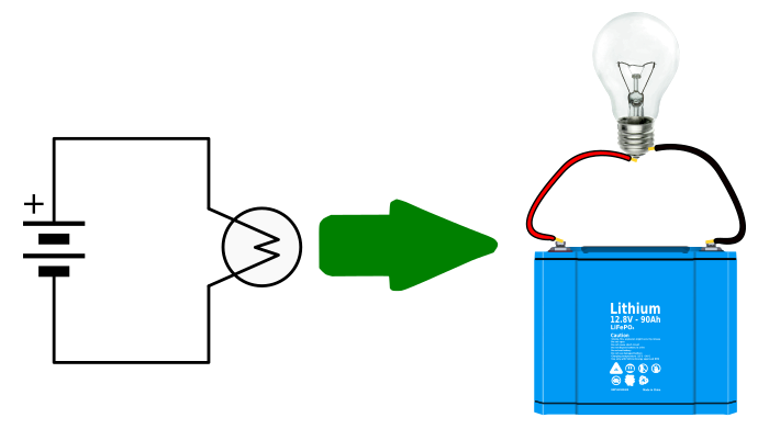
The power supply is shown at the top and the earth at the bottom to facilitate understanding of the current flow. The electrical symbol is used to describe all the installations in an electrical diagram. We'll go over all of the fundamental schematic symbols: A lamp is usually represented as a circle with a cross inside it. The ability to read electrical schematics is a really useful skill to have.
How To Read Circuit Diagrams For Beginners from startingelectronics.org A wiring diagram is a simple visual representation of the physical connections and physical layout of an electrical system or circuit. An electrical wiring diagram could be a single page schematic of how a ceiling fan should be connected to the power source and its remote switches. Basics 14 aov schematic (with block included) They're like a map for building or troubleshooting circuits, and can tell you almost everything you need to know to understand how a circuit works. Especially if you start messing around with building little electronics projects. It shows how the electrical wires are interconnected and can also show where fixtures and components may be connected to the system. As you examine individual control circuits and the The wiring diagram for this equipment is more difficult than those you studied in part 1—but again, the schematic as a whole can be simplified by breaking it down into its basic circuits.
A lamp is usually represented as a circle with a cross inside it.
Let's go back and have a look at the control panel, and try and figure out some of the connections by following a wiring diagram. Note that standard power sources are labeled with a circle that's filled with a plus or minus sign, while an ideal source looks like a circle with a horizontal line splitting it in half. This tutorial should turn you into a fully literate schematic reader! A wiring diagram is a simple visual representation of the physical connections and physical layout of an electrical system or circuit. Using the chassis symbol in this way invariably makes the diagram easier to read, because without 40 the symbol it would be necessary to show line connections between all those same points. Knowing how to read circuits is a very useful skill that will help you out all the time. We begin with a basics fuel pump & relay diagram See their number is in the horizontal axis and alphabets in the vertical axis. As i've mentioned in the previous articles , this is a control panel that is used for a system that turns wastewater into clean water. Single line diagram (sld) we usually depict the electrical distribution system by a graphic representation called a single line diagram (sld). As a layman view, sld is nothing but consisting of various components of the electrical system like, transformer, dg, panels consisting of ht breaker, lt breaker, ct, pt. This chapter discusses the common symbols used to depict the many components in electrical systems. Basics 9 4.16 kv pump schematic :
As a layman view, sld is nothing but consisting of various components of the electrical system like, transformer, dg, panels consisting of ht breaker, lt breaker, ct, pt. A large number of free template, 50000+ vector symbols, making professional chart so easy Circuit or schematic diagrams consist of symbols representing physical components and lines representing wires or electrical conductors. To reading these, you'll recognize common characteristics in all schematics. Scan over your schematics to figure out where your electrical currents are generated.
Reading A Wiring Diagram For Appliance Repair from www.appliance-repair-it.com Literally, a circuit is the path that allows electricity to flow. As a layman view, sld is nothing but consisting of various components of the electrical system like, transformer, dg, panels consisting of ht breaker, lt breaker, ct, pt. On it you can see some of the conventions used. We usually depict the electrical distribution system by a graphic representation called a single line diagram (sld). Note that standard power sources are labeled with a circle that's filled with a plus or minus sign, while an ideal source looks like a circle with a horizontal line splitting it in half. The box is marked with the numbers and alphabets followed by the page number. A lamp is usually represented as a circle with a cross inside it. Here i am giving the standard symbols used for the electrical relay diagram.in earlier days instead of plc or dcs like controllers relays are used as controllers.
Single line diagram (sld) we usually depict the electrical distribution system by a graphic representation called a single line diagram (sld).
To reading these, you'll recognize common characteristics in all schematics. Basics 13 valve limit switch legend : Schematics are our map to designing, building, and troubleshooting circuits. A first look at a circuit diagram may be confusing, but if you can read a subway map, you can read schematics. The power supply is shown at the top and the earth at the bottom to facilitate understanding of the current flow. As you examine individual control circuits and the A single line can show all or part of a system. It shows the components of the circuit as simplified shapes, and how to make the connections between the devices. Note that standard power sources are labeled with a circle that's filled with a plus or minus sign, while an ideal source looks like a circle with a horizontal line splitting it in half. To read and interpret electrical diagrams and schematics, the reader must first be well versed in what the many symbols represent. Let's go back and have a look at the control panel, and try and figure out some of the connections by following a wiring diagram. Here i am giving the standard symbols used for the electrical relay diagram.in earlier days instead of plc or dcs like controllers relays are used as controllers. This chapter discusses the common symbols used to depict the many components in electrical systems.
As i've mentioned in the previous articles , this is a control panel that is used for a system that turns wastewater into clean water. See their number is in the horizontal axis and alphabets in the vertical axis. Understanding how to read and follow schematics is an important skill for any electronics engineer. A large number of free template, 50000+ vector symbols, making professional chart so easy It shows how the electrical wires are interconnected and can also show where fixtures and components may be connected to the system.
How To Read Electrical Drawing In Hindi Yk Electrical Youtube from i.ytimg.com Literally, a circuit is the path that allows electricity to flow. The purpose is the same: The power supply is shown at the top and the earth at the bottom to facilitate understanding of the current flow. An electrical wiring diagram could be a single page schematic of how a ceiling fan should be connected to the power source and its remote switches. The wiring diagram for this equipment is more difficult than those you studied in part 1—but again, the schematic as a whole can be simplified by breaking it down into its basic circuits. A wiring diagram is a simple visual representation of the physical connections and physical layout of an electrical system or circuit. It shows how the electrical wires are interconnected and can also show where fixtures and components may be connected to the system. This chapter discusses the common symbols used to depict the many components in electrical systems.
A collection of such symbols in a diagram you appreciate immediately that all of them are actually one multiple electrical connection.
A large number of free template, 50000+ vector symbols, making professional chart so easy Getting from point a to point b. A car wiring diagram is a map. A single line can show all or part of a system. A wiring diagram is a simple visual representation of the physical connections and physical layout of an electrical system or circuit. To reading these, you'll recognize common characteristics in all schematics. How to read a electrical drawing 1. The electrical symbol is used to describe all the installations in an electrical diagram. Schematics are our map to designing, building, and troubleshooting circuits. Note that standard power sources are labeled with a circle that's filled with a plus or minus sign, while an ideal source looks like a circle with a horizontal line splitting it in half. Literally, a circuit is the path that allows electricity to flow. Gas/electric system, which is a relatively complex heating and cooling unit. See their number is in the horizontal axis and alphabets in the vertical axis.