Full Wave Rectifier Circuit Diagram In Multisim / Pcb Design Practical Bridge Rectifier Circuit Androiderode - 0 response to full wave bridge rectifier circuit multisim. Full wave bridge rectifier with a capacitor filter multisim live capacitor smoothing circuits calculations electronics notes. Half wave rectifier working circuit diagram applications title title study of diode rectifiers abstract a rectifier is an Circuit diagram of full wave rectifier. The positive terminal of two diodes is connected to the two ends of the transformer. Think about at what time point in a cycle the diode d4 sees piv.
First place down all your components. Ni multisim is a simulation and circuit design software of high standards,very useful for students,engineers and researchers.in this video we can understand. Full wave rectifier circuit diagram center tapped bridge rectifier 2a full wave bridge rectifier power supply with switch pcb full learn how to design pcb layout for specialty components and beyond The lower efficiency drawback of half wave rectifier can be overcome by using full wave rectifier. Full wave diode bridge¶ download this multisim design file for full wave diode bridge rectifier.
2 from The point c, diode d 1 conducts in forward direction as shown with the help of arrows. How to make a simple half wave rectifier circuit using multisim software. To reduce parasitic inductance and capacitance, i have connected the components as close as possible. Center tap divides the total secondary voltage into equal parts. Half wave rectifier working circuit diagram applications title title study of diode rectifiers abstract a rectifier is an Half wave rectifier and full wave rectifier. 📌 a differential amplifier is. The circuit i have produced should be a functional full wave bridge rectifier with a simple resistive filter but it is only reducing the magnitude of the output sinusoid as opposed to actually doing a full wave rectification.
Full wave rectifier circuit circuit diagram of full wave rectifier with capacitor filter.
To reduce parasitic inductance and capacitance, i have connected the components as close as possible. The lower efficiency drawback of half wave rectifier can be overcome by using full wave rectifier. Generally, all these blocks combination is called a regulated dc power supply that powers various electronic appliances. Center tap divides the total secondary voltage into equal parts. 💬 a capacitor is connected in parallel across the terminals of r1 to smooth out the rectified voltage. The point c, diode d 1 conducts in forward direction as shown with the help of arrows. Full wave bridge rectifier circuit multisim simulation docx qopo. First place down all your components. Full wave rectifier using a bridge rectifier Only one diode is used which conducts during positive cycle. Full wave rectifier circuit diagram center tapped bridge rectifier half wave rectifier circuit with diagram learn operation working lecture 4 ver2 diode app Pcb design for full wave rectifier using multisim software youtube. Multisim full how do i make and take measurements from a half wave rectifier circuit in multisim.
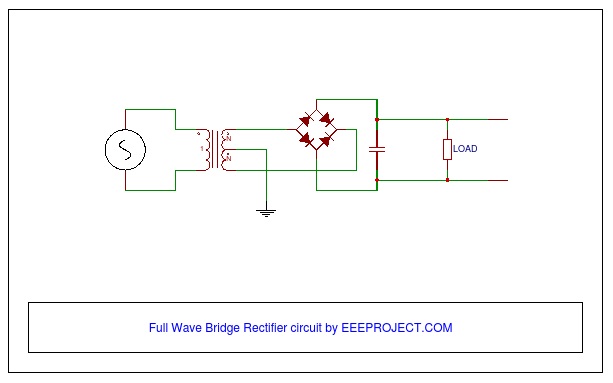
Full wave rectifier circuit diagram you can see that 4 diodes are connected in a bridge kind of structure and the oscilloscope is connected across the resistor to observe the voltage waveforms across the resistor. 💬 a capacitor is connected in parallel across the terminals of r1 to smooth out the rectified voltage. Think about at what time point in a cycle the diode d4 sees piv. 🔧 the switch connected to it may be toggled to see the effect it has on the output. How to make a simple half wave rectifier circuit using multisim software.
Full Wave Rectifier Circuit Working And Application from eeeproject.com In this circuit, we use two diodes, one for each half of the wave. Full wave rectifier circuit diagram in multisim › full wave rectifier circuit multisim. Full wave bridge rectifier circuit in multisim electrical. The circuit i have produced should be a functional full wave bridge rectifier with a simple resistive filter but it is only reducing the magnitude of the output sinusoid as opposed to actually doing a full wave rectification. Full wave rectifier circuit diagram center tapped bridge rectifier half wave rectifier circuit with diagram learn operation working lecture 4 ver2 diode app Ni multisim is a simulation and circuit design software of high standards,very useful for students,engineers and researchers.in this video we can understand. Ctrl + w opens up the component window. To reduce parasitic inductance and capacitance, i have connected the components as close as possible.
Half wave rectifier and full wave rectifier.
Full wave rectifier using a bridge rectifier Piv is the maximum possible voltage across a diode during its reverse biased period. Rectifier broadly divided into two categories: Ctrl + w opens up the component window. How to make a simple half wave rectifier circuit using multisim software. In this circuit, we use two diodes, one for each half of the wave. Run the simulation by pressing the run button. I made it based on this diagram provided to me by my. For this demonstration, the circuit is constructed in a solderless breadboard, with the help of the schematic; Full wave bridge rectifier circuit in multisim. Full wave bridge rectifier circuit multisim simulation docx qopo. The point c, diode d 1 conducts in forward direction as shown with the help of arrows. 💬 a capacitor is connected in parallel across the terminals of r1 to smooth out the rectified voltage.
Thus, this type of rectifier where centre tapping is provided is called centre tap rectifier. Working principle of half wave rectifier: Form there you can place down your components. Full wave rectifier circuit circuit diagram of full wave rectifier with capacitor filter. Only one diode is used which conducts during positive cycle.
Full Wave Bridge Rectifier Multisim Live from www.multisim.com Center tap divides the total secondary voltage into equal parts. To reduce parasitic inductance and capacitance, i have connected the components as close as possible. Full wave rectifier diagram full wave rectifier theory. Full wave diode bridge¶ download this multisim design file for full wave diode bridge rectifier. These can be individual diodes, or it is also easy to obtain bridge rectifiers as a single electronic component. Another half cycle of ac voltage (negative cycle) is not used. For this demonstration, the circuit is constructed in a solderless breadboard, with the help of the schematic; Part 1 covers the entry of a schematic diagram that represents the circuit, a process also known as schematic capture.
Full wave bridge rectifier circuit multisim simulation docx.
First place down all your components. Generally, all these blocks combination is called a regulated dc power supply that powers various electronic appliances. Full wave rectifier circuit circuit diagram of full wave rectifier with capacitor filter. Full wave rectifier circuit diagram you can see that 4 diodes are connected in a bridge kind of structure and the oscilloscope is connected across the resistor to observe the voltage waveforms across the resistor. The circuit i have produced should be a functional full wave bridge rectifier with a simple resistive filter but it is only reducing the magnitude of the output sinusoid as opposed to actually doing a full wave rectification. Multisim full how do i make and take measurements from a half wave rectifier circuit in multisim. Ni multisim is a simulation and circuit design software of high standards,very useful for students,engineers and researchers.in this video we can understand. I made it based on this diagram provided to me by my. Half wave rectifier working circuit diagram applications title title study of diode rectifiers abstract a rectifier is an Full wave diode bridge¶ download this multisim design file for full wave diode bridge rectifier. 3 full wave rectifier circuit in multisim full circuit rectifier Circuit diagram of full wave rectifier. Working principle of half wave rectifier: