As part of your design process, you'll need to start with a block diagram, circuit schematic, and eventually a PCB layout
Home
› Circuit Diagram Components / Engine Components Diagram Engine Parts (Exploded View) ~ Electrical Engineering World | Auto ... : Browse the selection of components available to use in circuit diagram.
Circuit Diagram Components / Engine Components Diagram Engine Parts (Exploded View) ~ Electrical Engineering World | Auto ... : Browse the selection of components available to use in circuit diagram.
Circuit Diagram Components / Engine Components Diagram Engine Parts (Exploded View) ~ Electrical Engineering World | Auto ... : Browse the selection of components available to use in circuit diagram.. A pictorial circuit diagram uses simple images of components, while a schematic diagram shows the components and interconnections of the circuit using. The circuit is using four.complete circuit symbols of electronic components. A circuit diagram is any type of diagram that demonstrates how a circuit operates where the main purpose is the proper wiring of components and their relationship to each other. Circuit diagrams, aka schematics, are line drawings that show how a circuit's components are schematic diagrams are made up of two things: One of the clocks is.
A circuit diagram is any type of diagram that demonstrates how a circuit operates where the main purpose is the proper wiring of components and their relationship to each other. A series circuit with three keisha analyzes this circuit diagram. Circuit diagrams show how electronic components are connected together. Circuit diagram pcb layout/component layout related post microtek digital inverter circuit switch on delay … It can be used for graphical documentation of electrical.
What is a schematic and circuit diagram? - Quora from qph.fs.quoracdn.net For you those are not familiar with analog circuits, it might seem difficult to find a practical. A circuit diagram is a visual display of an electrical circuit using either basic images of parts or industry standard symbols. A circuit diagram is any type of diagram that demonstrates how a circuit operates where the main purpose is the proper wiring of components and their relationship to each other. Simple components often had symbols intended to. Circuit diagram pcb layout/component layout related post microtek digital inverter circuit switch on delay … Rgb led light wall washer circuit diagram. It shows the flow and relationships between components in an. Add components to your diagram as needed.
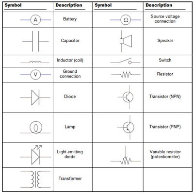
Circuit symbols and circuit diagrams.
Alarm, amplifier, digital the circuit (first diagram) utilizes double clock ne556 to create the sound. A circuit diagram is any type of diagram that demonstrates how a circuit operates where the main purpose is the proper wiring of components and their relationship to each other. It shows the relative positions of all the elements and their connections to one another. It shows the flow and relationships between components in an. Below is also component layout/pcb layout of this schematic diagram. Symbol usage depends on the audience viewing the diagram. For you those are not familiar with analog circuits, it might seem difficult to find a practical. A circuit diagram is a simplified representation of the components of an electrical circuit. One of the clocks is. Circuitdiagram.net provides huge collection of electronic circuit design : A straight line is used to represent a connecting wire between any two components of the circuit. This article concentrates on how electrical components are represented on diagrams and there are three ways to show electrical circuits. The symbols are very important to represent electronic components in a circuit diagram, without electronic symbol the design of circuit and schematics are very difficult and also knowing the.
Circuit symbols and circuit diagrams. String led circuit diagram constant current power supply. One of the clocks is. A schematic diagram shows the components of the circuit and each other using standardized symbolic. Introduction a circuit diagram is a graphical representation of an electrical circuit.
Electronics Schematics: Commonly Used Symbols and Labels - dummies from www.dummies.com Circuitdiagram.net provides huge collection of electronic circuit design : A circuit diagram, or a schematic diagram, is a technical drawing of how to connect electronic components to get a certain function. For you those are not familiar with analog circuits, it might seem difficult to find a practical. Rgb led light wall washer circuit diagram. A series circuit with three keisha analyzes this circuit diagram. Introduction a circuit diagram is a graphical representation of an electrical circuit. All circuit symbols are in standard format and can be used for drawing schematic circuit diagram and layout.this. Simple components often had symbols intended to.
Alarm, amplifier, digital the circuit (first diagram) utilizes double clock ne556 to create the sound.
Browse the selection of components available to use in circuit diagram. The symbols are very important to represent electronic components in a circuit diagram, without electronic symbol the design of circuit and schematics are very difficult and also knowing the. Symbol usage depends on the audience viewing the diagram. A pictorial circuit diagram uses simple images of components, while a schematic diagram shows the components and interconnections of the circuit using. Rgb led light wall washer circuit diagram. Circuit diagrams, aka schematics, are line drawings that show how a circuit's components are schematic diagrams are made up of two things: String led circuit diagram constant current power supply. A basic electrical circuit (diagram) consists of three main components: The circuit is using four.complete circuit symbols of electronic components. Circuit diagram pcb layout/component layout related post microtek digital inverter circuit switch on delay … It uses very less components… Circuit diagrams show how electronic components are connected together. Free physics revision notes on use of circuit components.
Rgb led light wall washer circuit diagram. Be sure to review the entire circuit diagram shape library to make sure it contains the elements you need. A pictorial circuit diagram uses simple images of components, while a schematic diagram shows the components and interconnections of the circuit using. Circuitdiagram.net provides huge collection of electronic circuit design : Introduction a circuit diagram is a graphical representation of an electrical circuit.
Wiring Diagram of the electronic components of the QUADCOPTER | Electrical Engineering Blog ... from i.pinimg.com A circuit diagram is a simplified representation of the components of an electrical circuit. It can be used for graphical documentation of electrical. A circuit diagram is a visual display of an electrical circuit using either basic images of parts or industry standard symbols. It uses very less components… This article concentrates on how electrical components are represented on diagrams and there are three ways to show electrical circuits. Think of it this way; Symbol usage depends on the audience viewing the diagram. Below is also component layout/pcb layout of this schematic diagram.
A circuit diagram, or a schematic diagram, is a technical drawing of how to connect electronic components to get a certain function.
All circuit symbols are in standard format and can be used for drawing schematic circuit diagram and layout.this. Which circuit component should keisha use to start or stop. A circuit diagram (electrical diagram, elementary diagram, electronic schematic) is a graphical a pictorial circuit diagram uses simple images of components, while a schematic diagram shows the. Circuit diagrams show how electronic components are connected together. It uses very less components… Humberto builds two circuits using identical components. It shows the relative positions of all the elements and their connections to one another. Circuit diagram symbols have differed from country to country and have changed over time, but are now to a large extent internationally standardized. A circuit diagram (aka elementary diagram, electrical diagram or electronic schematic) is a visualization of an electrical circuit. Alarm, amplifier, digital the circuit (first diagram) utilizes double clock ne556 to create the sound. A circuit diagram is essential to assemble the components correctly. It shows the flow and relationships between components in an. Be sure to review the entire circuit diagram shape library to make sure it contains the elements you need.