As part of your design process, you'll need to start with a block diagram, circuit schematic, and eventually a PCB layout
Home
› Full Subtractor Logic Diagram And Truth : Full Subtractor Symbol Electronic Schematics Full Arduino - Theory subtractor circuits take two binary numbers as input and subtract one binary number input from the other it accepts three inputs:
Full Subtractor Logic Diagram And Truth : Full Subtractor Symbol Electronic Schematics Full Arduino - Theory subtractor circuits take two binary numbers as input and subtract one binary number input from the other it accepts three inputs:
Full Subtractor Logic Diagram And Truth : Full Subtractor Symbol Electronic Schematics Full Arduino - Theory subtractor circuits take two binary numbers as input and subtract one binary number input from the other it accepts three inputs:. Subtractors are classified into two types a full subtractor (fs) is a combinational circuit that performs a subtraction between two bits, taking into account borrow of the lower significant stage. Select 2 variables as your select line. Cascading of full subtractor circuit. If you like geeksforgeeks and would like to contribute, you. A full subtractor circuit is a combinational circuit that performs a subtraction between two bits, taking into account borrow of the lower significant stage.
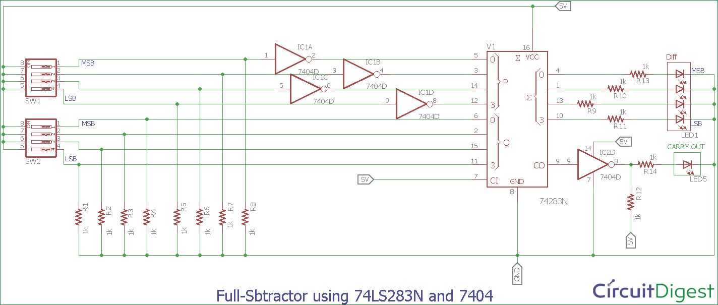
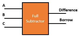
Binary subtractor.the block model, truth table and logic diagram of a half subtractor shown in above figure.acquista per non rimanere deluso.in this implementation, carry of each full adder is connected. There are two types of subtractors. In the above image, instead of block diagram, actual symbols are shown. The circuit is assembled as per the circuit diagram. Full subtractor performs subtraction of two bits, one is minuend and other is subtrahend.
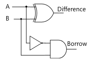
Virtual Labs from de-iitr.vlabs.ac.in Full subtractor is a combinational circuit that perform subtraction of three input bits namely minuend bit a, subtrahend bit b, and borrow in c. As your logic circuits (as well as the associated truth tables and equations) get larger and more here's the truth table and corresponding maps for the full subtractor, which takes into account an from the half subtractor, we have various pieces of this, and can do the same thing we did with the. Draw truth table and logic diagram of full subtractor. Makes no sense at all. The logic symbol and truth table are. If you like geeksforgeeks and would like to contribute, you. When logic is 0 at m line addition will takes place. This is executed till 100 ns, which is the the logic diagram includes an and gate and two half subtractor circuits, which are further an or, xor.
Full subtractor performs subtraction of two bits, one is minuend and other is subtrahend.
Classece6332spring17alu uva ece bme wiki. A subtractor is a digital logic circuit in electronics that performs the operation of subtraction of two number. How does subtractor circuit work. Theory subtractor circuits take two binary numbers as input and subtract one binary number input from the other it accepts three inputs: Minuend, subtrahend and a borrow bit and it produces two outputs: Subtractor is the one which used to subtract two binary number(digit) and provides difference and borrow as a output.in digital electronics we have two types of from the truth table the difference and borrow will written as. Dip switches and resistors are connected to the inputs and led's are connected to the outputs. Full subtractor in digital logic geeksforgeeks. The half subtractors designed can be used in the the subtractor designed by logic gates is described below. Full subtractor definition, block diagram, truth table, circuit diagram, logic diagram, boolean expression and equation are discussed. And full subtractor in simulator 2. As the full subtractor circuit above represents two half subtractors cascaded together, the truth table for the full subtractor will have eight different input combinations as there are 4 3. A full subtractor circuit is a combinational circuit that performs a subtraction between two bits, taking into account borrow of the lower significant stage.
Start with the truth table of full subtractor. How does subtractor circuit work. It gives two outputs, subtraction and borrow. When logic is 0 at m line addition will takes place. Full subtractor combinational logic circuits electronics tutorial.
Full Subtractor Circuit And Its Construction from circuitdigest.com There are two types of subtractors. In the above image, instead of block diagram, actual symbols are shown. The logic symbol of half subtractor is represented in the diagram below. Hexadecimal display is also connected to output. The half subtractors designed can be used in the construction of full subtractors. How does subtractor circuit work. This article is contributed by harshita pandey. By using any full subtractor logic circuit.
A full subtractor subtracts two bits a from b, along with previous borrow bin.
Full subtractor in digital logic geeksforgeeks. Cascading of full subtractor circuit. Power of 5v is applied at. The difference d and borrow out bout. The full subtractor generates two output bits: Binary addition and subtraction.logic diagram for full subtractor.full adder logic diagram. In the above image, instead of block diagram, actual symbols are shown. Full subtractor definition, block diagram, truth table, circuit diagram, logic diagram, boolean expression and equation are discussed. A half subtractor is a logical circuit that performs a subtraction operation on two binary digits. Logic diagram for full subtractor. A full subtractor subtracts two bits a from b, along with previous borrow bin. When logic is 0 at m line addition will takes place. Subtractor circuits take two binary numbers as input and subtract one binary number input from the other binary number input.
Full subtractor combinational logic circuits electronics tutorial. A full subtractor circuit is a combinational circuit that performs a subtraction between two bits, taking into account borrow of the lower significant stage. Power of 5v is applied at. This is executed till 100 ns, which is the the logic diagram includes an and gate and two half subtractor circuits, which are further an or, xor. There are two types of subtractors.
Full Subtractor Truth Table Logic Diagram Electricalvoice from electricalvoice.com The circuit is assembled as per the circuit diagram. The half subtractors designed can be used in the the subtractor designed by logic gates is described below. Subtractor circuits take two binary numbers as input and subtract one binary number input from the other binary number input. When logic is 0 at m line addition will takes place. A full subtractor circuit is a combinational circuit that performs a subtraction between two bits, taking into account borrow of the lower significant stage. For example b and c in my case. **draw truth table and logic diagram of full subtractor.** the full subtractor is a combinational circuit with three inputs a, b and bin and two outputs d and bo. Full subtractor is a combinational logic circuit used for the purpose of subtracting two single bit numbers with a borrow.
If you like geeksforgeeks and would like to contribute, you.
A is the minuend, b is the subtrahend, bin is the borrow produced by the previous state. Dip switches and resistors are connected to the inputs and led's are connected to the outputs. Full subtractor is a combinational circuit that perform subtraction of three input bits namely minuend bit a, subtrahend bit b, and borrow in c. As your logic circuits (as well as the associated truth tables and equations) get larger and more here's the truth table and corresponding maps for the full subtractor, which takes into account an from the half subtractor, we have various pieces of this, and can do the same thing we did with the. Logic diagram for full subtractor. Minuend, subtrahend and a borrow bit and it produces two outputs: For example b and c in my case. Select 2 variables as your select line. Full subtractor definition circuit diagram truth table. Makes no sense at all. The half subtractors designed can be used in the the subtractor designed by logic gates is described below. A half subtractor is a logical circuit that performs a subtraction operation on two binary digits. Previously, we have discussed an overview of this like construction, circuit diagram with logic gates.