As part of your design process, you'll need to start with a block diagram, circuit schematic, and eventually a PCB layout
Home
› Outlet Wiring Diagrams - Wiring Diagram For Light Switch And Outlet Combo / Diagram spa gfci breaker wiring full version hd quality diagramacion rockwebradio it.
Outlet Wiring Diagrams - Wiring Diagram For Light Switch And Outlet Combo / Diagram spa gfci breaker wiring full version hd quality diagramacion rockwebradio it.
Outlet Wiring Diagrams - Wiring Diagram For Light Switch And Outlet Combo / Diagram spa gfci breaker wiring full version hd quality diagramacion rockwebradio it.. Wiring a new 220 outlet is a project that someone who has experience working with electricity can do safely by working carefully and following the proper precautions. Universal single stage wiring diagram.ai created date: You don't ever want to work on basic house wiring in your house with the power on. Wiring diagram for multiple outlets this diagram shows the wiring for multiple receptacles in an arrangement that connects each individually to the source. A grounded contact at the bottom, center is crescent shaped.
As shown in the fig, the switch is firstly installed in the wiring the hot wire from switch feeds all the other parallel connected outlets hence, the outlet on/off operation can be controlled through the switch. Wiring a new 220 outlet is a project that someone who has experience working with electricity can do safely by working carefully and following the proper precautions. The tab between the neutral, silver terminals should remain intact. Most arc welders require a dedicated electrical circuit and 220 volt outlet that is sized according to the specifications of the welder as. The black wire from the switch connects to the hot on the receptacle.
2 Way Light Switch Wiring Diagram House Electrical Wiring Diagram from 4.bp.blogspot.com For wiring in series, the terminal screws are the means for passing voltage from one receptacle to another. The black wire (line) and white (neutral) connect to the receptacle terminals and another 2 wire nm that travels to the next receptacle. How to install a 220 volt outlet askmediy. Any break or malfunction in one outlet will cause all the other outlets to fail. A switch loop with an available neutral wire is used to control the light which complies with nec 2011 requirements. In this case, the circuit load flows both to the receptacle and to any downstream receptacles without being dependent on flowing through the receptacle's connecting tab. Diagram spa gfci breaker wiring full version hd quality diagramacion rockwebradio it. The long slot on the left is the neutral contact and the short slot is the hot contact.
If you are replacing an existing gfci outlet with a new one we suggest that you read our page about replacing a gfci outlet.
The above light switch wiring diagram depicts the power from the circuit breaker panel going to an electrical receptacle outlet and then continues to the next outlet and then to a single pole wall switch and then to another outlet. This document and the designs or information contained within are the sole property of nitrous outlet and may not be copied, distributed or made available to others without permission. Wiring diagram for multiple outlets this diagram shows the wiring for multiple receptacles in an arrangement that connects each individually to the source. The tab between the neutral, silver terminals should remain intact. This wiring diagram illustrates adding wiring for a light switch to control an existing wall outlet. The long slot on the left is the neutral contact and the short slot is the hot contact. In this wiring diagram, the builtin switch in the combo device controls a lighting point whereas, outlet can be used for other loads. For wiring in series, the terminal screws are the means for passing voltage from one receptacle to another. A grounded contact at the bottom, center is crescent shaped. Wiring a breaker box bo diagram rg 220 full wall plug 240 1996 50 amp gfci 115v fusebox and how to install volt circuit 30 outlet switched diagrams with wire dryer home electric information the 110v tos diy spa get wired an light switch for your electrical system explained 20 100 fuse garage sub panel 240v. The black wire from the switch connects to the hot on the receptacle. How to wire gfci outlets. Gfci switch outlet wiring diagrams do for switched wall wire a half hot leviton gfi combo diagram page 1 20a with light i turn off the advice and controlled an to control overhead split receptacles electrical 101 how 31 common household circuit wirings you controlling branch design device receptacle installing testing outdoor 15 amp 125 volt self test 3 gang.
In this wiring diagram, the builtin switch in the combo device controls a lighting point whereas, outlet can be used for other loads. Understanding switched outlet wiring for home electrical applications the switched outlet wiring configurations show two different wiring scenarios which are most commonly used. The receptacle is split by breaking the connecting tab between the two, brass colored terminals. If you are replacing an existing gfci outlet with a new one we suggest that you read our page about replacing a gfci outlet. Wiring a gfci receptacle is a little more complicated than hooking up a regular outlet but easily learned once explained.
50 Amp Wiring Diagram Irv2 Forums from www.irv2.com In this wiring diagram, the builtin switch in the combo device controls a lighting point whereas, outlet can be used for other loads. How to wire gfci outlets. The long slot on the left is the neutral contact and the short slot is the hot contact. The black wire from the switch connects to the hot on the receptacle. Wiring a new 220 outlet is a project that someone who has experience working with electricity can do safely by working carefully and following the proper precautions. Wiring diagram for a split outlet this diagram illustrates the wiring for a split receptacle with the top half controlled by sw1 and the bottom half always hot. You don't ever want to work on basic house wiring in your house with the power on. This is a standard 15 amp, 120 volt wall receptacle outlet wiring diagram.
The long slot on the left is the neutral contact and the short slot is the hot contact.
This repeats until the end of the chain. How to install a 220 volt outlet askmediy. In this case, the circuit load flows both to the receptacle and to any downstream receptacles without being dependent on flowing through the receptacle's connecting tab. The long slot on the left is the neutral contact and the short slot is the hot contact. This is a polarized device. To add an additional outlet to the combo device, simple connect the line, neutral and ground terminals as shown in the fig below. The hot source wire is removed from the receptacle and spliced to the red wire running to the switch. Single pole light switch wiring diagram with electrical outlets connected. The above light switch wiring diagram depicts the power from the circuit breaker panel going to an electrical receptacle outlet and then continues to the next outlet and then to a single pole wall switch and then to another outlet. Universal single stage wiring diagram.ai created date: Diagram spa gfci breaker wiring full version hd quality diagramacion rockwebradio it. The video covers how to strip electrical wire, create loops on the load, neutral, and ground wire, and how to. The long slot on the left is the neutral contact and the short slot is the hot contact.
This is a standard 15 amp, 120 volt wall receptacle outlet wiring diagram. A switch loop with an available neutral wire is used to control the light which complies with nec 2011 requirements. The black wire from the switch connects to the hot on the receptacle. Universal single stage wiring diagram.ai created date: Switched outlet wiring diagram depicts the electrical power from the circuit breaker panel entering the switched electrical receptacle outlet box where a two wire cable goes to the switch and another two wire cable feeds power to another outlet that is live at all times.
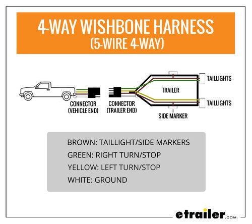
Wiring Trailer Lights With A 4 Way Plug It S Easier Than You Think Etrailer Com from www.etrailer.com The long slot on the left is the neutral contact and the short slot is the hot contact. In this wiring diagram, the builtin switch in the combo device controls a lighting point whereas, outlet can be used for other loads. Understanding switched outlet wiring for home electrical applications the switched outlet wiring configurations show two different wiring scenarios which are most commonly used. Any break or malfunction in one outlet will cause all the other outlets to fail. Diagram spa gfci breaker wiring full version hd quality diagramacion rockwebradio it. The receptacle is split by breaking the connecting tab between the two, brass colored terminals. A switch loop with an available neutral wire is used to control the light which complies with nec 2011 requirements. Most arc welders require a dedicated electrical circuit and 220 volt outlet that is sized according to the specifications of the welder as.
The video covers how to strip electrical wire, create loops on the load, neutral, and ground wire, and how to.
All wires are spliced to a pigtail which is connected to each device separate from all the others in the row. The video covers how to strip electrical wire, create loops on the load, neutral, and ground wire, and how to. Wiring a gfci receptacle is a little more complicated than hooking up a regular outlet but easily learned once explained. Switched outlet wiring diagram depicts the electrical power from the circuit breaker panel entering the switched electrical receptacle outlet box where a two wire cable goes to the switch and another two wire cable feeds power to another outlet that is live at all times. Wiring a breaker box bo diagram rg 220 full wall plug 240 1996 50 amp gfci 115v fusebox and how to install volt circuit 30 outlet switched diagrams with wire dryer home electric information the 110v tos diy spa get wired an light switch for your electrical system explained 20 100 fuse garage sub panel 240v. The receptacle is split by breaking the connecting tab between the two, brass colored terminals. Is there a diagram showing all the wires coming to t5225 and running through light fixture. The wiring diagram above shows how switched outlets are often wired. Single pole light switch wiring diagram with electrical outlets connected. You don't ever want to work on basic house wiring in your house with the power on. Gfci switch outlet wiring diagrams do for switched wall wire a half hot leviton gfi combo diagram page 1 20a with light i turn off the advice and controlled an to control overhead split receptacles electrical 101 how 31 common household circuit wirings you controlling branch design device receptacle installing testing outdoor 15 amp 125 volt self test 3 gang. However, working on your circuit breaker box and electrical system can lead to serious injury or death if you don't know what you're doing, so hire an electrician if you don. The black wire (line) and white (neutral) connect to the receptacle terminals and another 2 wire nm that travels to the next receptacle.