As part of your design process, you'll need to start with a block diagram, circuit schematic, and eventually a PCB layout
Home
› Electric Brake Wiring Diagram / Wiring Diagram For Trailer Brake Controller - Database - Wiring Diagram Sample : Blue = electric brakes or hydraulic reverse disable (see blue wire notes below.) in the trailer wiring diagram and connector application chart below, use the first 5 pins, and ignore the rest.
Electric Brake Wiring Diagram / Wiring Diagram For Trailer Brake Controller - Database - Wiring Diagram Sample : Blue = electric brakes or hydraulic reverse disable (see blue wire notes below.) in the trailer wiring diagram and connector application chart below, use the first 5 pins, and ignore the rest.
Electric Brake Wiring Diagram / Wiring Diagram For Trailer Brake Controller - Database - Wiring Diagram Sample : Blue = electric brakes or hydraulic reverse disable (see blue wire notes below.) in the trailer wiring diagram and connector application chart below, use the first 5 pins, and ignore the rest.. Important facts to remember 1. Locate the trailer connector's blue wire that supplies power to the electric brakes. Basics 10 480 v pump schematic : Important facts to remember 1. A trailer brake controller displays the voltage level on the wiring traveling from your truck's brake pedal to the trailer's electric brakes.
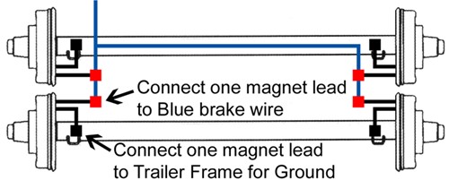
Blue = electric brakes or hydraulic reverse disable (see blue wire notes below.) in the trailer wiring diagram and connector application chart below, use the first 5 pins, and ignore the rest. You may have to cut into the trailer wiring's sheathing to find the wire. A single trick that we 2 to print out exactly the same wiring plan off twice. Connect the breakaway switch's other lead to the blue wire with a scotchlok connector. The service brake circuit must be disconnected from an existing trailer plug.
Trailer Wiring Diagram With Electric Brakes | Wiring Diagram from annawiringdiagram.com The brake control must be installed with a 12 volt negative ground system. Read and follow all instructions carefully before wiring brake control. Route the elecbrakes cable as required, if you internally. Print the wiring diagram off in addition to use highlighters to be able to trace the circuit. The four wires control the turn signals, brake lights and taillights or running lights. Collection of wiring diagram for utility trailer with electric brakes. Basics 10 480 v pump schematic : On the 1 o'clock side it will have a banjo looking fitting (shown to the left).
Connect the breakaway switch's other lead to the blue wire with a scotchlok connector.
Collection of wiring diagram for utility trailer with electric brakes. A single trick that we 2 to print out exactly the same wiring plan off twice. Basics 10 480 v pump schematic : This article will be talking wiring electric trailer brakes diagram.which are the advantages of knowing such knowledge? Print the wiring diagram off in addition to use highlighters to be able to trace the circuit. Diagram travel trailer electric brake wiring full version hd quality rediagram amicideidisabilionlus it. Basics 9 4.16 kv pump schematic : Generic wiring diagram read this first: Important facts to remember 1. Ensure it is sealed off and cannot create a short circuit with any other wire or the chassis. We then run a jumper wire from the electric brake power wire to the right side brake assemblies (see photo). Read and follow all instructions carefully before wiring brake control. As the name implies, they use four wires to carry out the vital lighting functions.
The four wires control the turn signals, brake lights and taillights or running lights. The brake control must be installed with a 12 volt negative ground system. Basics 10 480 v pump schematic : When you employ your finger or perhaps stick to the circuit together with your eyes, it is easy to mistrace the circuit. Wiring instructions for electronic brake controls p/n 4399 rev k generic wiring diagram read this first:
Wiring Diagram For Trailer Brake Controller - Database - Wiring Diagram Sample from tonetastic.info Trailer wiring connectors various connectors are available from four to seven pins that allow for the transfer of power for the lighting as well as auxiliary functions such as an electric trailer brake controller, backup lights, or a 12v power supply for a winch or interior trailer lights. You may have to cut into the trailer wiring's sheathing to find the wire. We then run a jumper wire from the electric brake power wire to the right side brake assemblies (see photo). Generic wiring diagram read this first: Ensure it is sealed off and cannot create a short circuit with any other wire or the chassis. Important facts to remember 1. Important facts to remember 1. Wiring gets a little more complicated when you tow larger or more sophisticated trailers.
Blue = electric brakes or hydraulic reverse disable (see blue wire notes below.) in the trailer wiring diagram and connector application chart below, use the first 5 pins, and ignore the rest.
Read and follow all instructions carefully before wiring brake control. Blue = electric brakes or hydraulic reverse disable (see blue wire notes below.) in the trailer wiring diagram and connector application chart below, use the first 5 pins, and ignore the rest. This short video is about trailer brakes, electric brakes and wiring. The brake control must be installed with a 12 volt negative ground. Locate the trailer connector's blue wire that supplies power to the electric brakes. The service brake circuit must be disconnected from an existing trailer plug. Basics 14 aov schematic (with block included) basics 15 wiring (or connection. How electric trailer brakes work. It reveals the elements of the circuit as streamlined forms, and also the power and signal connections between the gadgets. You should be getting at maximum: A trailer brake controller displays the voltage level on the wiring traveling from your truck's brake pedal to the trailer's electric brakes. White pin to your floor. Jeep grand cherokee electric brake control wiring.
Dexter axle brake actuator k71 651 how to wire the electric over a trailer for brakes wiring diagram hayes full testing magnets airstream forums hydraulic disc 00 installing on your dodge neo trailers manual do compare vs travel 12 x 2 assembly nev r adjust 25 3 375 10 box dummies pelican. The brake control must be installed with a 12 volt negative ground system. Locate the trailer connector's blue wire that supplies power to the electric brakes. The brake control must be installed with a 12 volt negative ground system. A wiring diagram is a streamlined traditional pictorial representation of an electrical circuit.
Released 7 Wire Trailer Electric Brake Wiring Diagram read online ~ 247 Download Kindle from www.etrailer.com This article will be talking wiring electric trailer brakes diagram.which are the advantages of knowing such knowledge? Basics 9 4.16 kv pump schematic : The brake control must be installed with a 12 volt negative ground. As the name implies, they use four wires to carry out the vital lighting functions. A single trick that we 2 to print out exactly the same wiring plan off twice. Keep these instructions with the brake control for future reference. It also talks about electric brake controller.thanks for watching ! Important facts to remember 1.
Keep these instructions with the brake control for future reference.
A trailer brake controller displays the voltage level on the wiring traveling from your truck's brake pedal to the trailer's electric brakes. Blue = electric brakes or hydraulic reverse disable (see blue wire notes below.) in the trailer wiring diagram and connector application chart below, use the first 5 pins, and ignore the rest. The fsa brakes will have a wire that will run from about 9 o'clock to 1 o'clock. You may have to cut into the trailer wiring's sheathing to find the wire. Dexter axle brake actuator k71 651 how to wire the electric over a trailer for brakes wiring diagram hayes full testing magnets airstream forums hydraulic disc 00 installing on your dodge neo trailers manual do compare vs travel 12 x 2 assembly nev r adjust 25 3 375 10 box dummies pelican. Over 10+ visual representation of components and diagrams associated to electric trailer brake wiring diagram, every picture helps and easy to understand. Keep these instructions with the brake control for future reference. Important facts to remember 1. Jeep grand cherokee electric brake control wiring. Trailer wiring diagrams trailer wiring connectors various connectors are available from four to seven pins that allow for the transfer of power for the lighting as well as auxiliary functions such as an electric trailer brake controller, backup lights, or a 12v power supply for a winch or interior trailer lights. The service brake circuit must be disconnected from an existing trailer plug. Connect your blue wire (which is the one that controls brakes) to the multimeter with an ammeter setting between the brake controller and trailer connector. Collection of wiring diagram for utility trailer with electric brakes.