As part of your design process, you'll need to start with a block diagram, circuit schematic, and eventually a PCB layout
Home
› Light Circuit Diagram / Lighting Circuit Diagrams For 1 2 And 3 Way Switching - Here is a simple led night light circuit which can be used as a room night lamp.
Light Circuit Diagram / Lighting Circuit Diagrams For 1 2 And 3 Way Switching - Here is a simple led night light circuit which can be used as a room night lamp.
Light Circuit Diagram / Lighting Circuit Diagrams For 1 2 And 3 Way Switching - Here is a simple led night light circuit which can be used as a room night lamp.. Each bulb connected through separate line (also known as live or phase) and neutral wire. The transistor is the only active component which is positioned as a switch for preventing the battery voltage from reaching the connected leds during day time. And the only way to change the. The hot and neutral terminals on each fixture are spliced with a pigtail to the circuit wires which then continue on to the next light. This diagram illustrates wiring for one switch to control 2 or more lights.
Here is a simple led night light circuit which can be used as a room night lamp. This would be cable a in the diagram below (fig 2) which shows how the ceiling rose is terminated. 55 chevy turn signal wiring 1955 ignition switch 57 diagram. Each bulb connected through separate line (also known as live or phase) and neutral wire. The circuit is using four leds to perform as a night lamp.
Engineer An Led Night Light Science Project from cdn.sciencebuddies.org Step by step instructions on how to wire a switched outlet. Mar 09, 21 09:56 pm. A cable is run from the junction box to the light, usually via a ceiling rose. The power we will use for this circuit is a 3 volts, which can be obtained from either 2 'aa' batteries in series or from a dc power supply set to this voltage. I designed the circuit around an inverter. Want to turn a lamp on with a light switch? If it gets a high voltage in, it gives a low voltage out. However, this is a great time to look at the difference between series and parallel circuits.
In the above fig, it is clearly shows that all the light bulbs are connected in parallel i.e.
Mar 09, 21 09:56 pm. Switches are shown as dotted rectangles. You will even find symbols showing the location of smoke detectors, your doorbell. The circuit uses an op amp as voltage comparator. This circuit is from my free email course on how to make a light blink. The hot and neutral terminals on each fixture are spliced with a pigtail to the circuit wires which then continue on to the next light. These are only schematic diagrams to explain about the different kinds of arrangements that you may find when changing a light fitting. The physical circuit for the above circuit diagram may look something like the image below, although a more practical physical circuit would have a light bulb holder and clamps that connect to the battery terminals. I designed the circuit around an inverter. Need help wiring a 3 way switch? Light bulb and switch wiring diagram. The circuit is simple and can be built with few components. Garden lights incorporate three basic circuits, the charging circuit, the dark detecting circuit that turns the led driver on and off, and the led driver.
A high voltage is a voltage close to the supply voltage. You will even find symbols showing the location of smoke detectors, your doorbell. Wiring a single pole light switch. In this circuit, we will try to connect three 5mm white leds in parallel and light them up using a 12v supply. The circuit diagram for leds in parallel connection is shown in the following image.
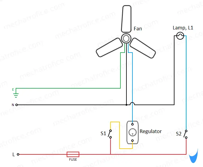
Ceiling Fan And Light Wiring Circuit Diagram from mechatrofice.com You will even find symbols showing the location of smoke detectors, your doorbell. Light switch wiring diagram will hopefully help you finish a project and impress your friends. 1n4007 diodes are used in the circuit to Light bulb and switch wiring diagram. This light switch wiring diagram page will help you to master one of the most basic do it yourself projects around your house. In parallel circuits, each light has its own circuit, so all but one light could be burned out, and the last one will still function. Garden lights incorporate three basic circuits, the charging circuit, the dark detecting circuit that turns the led driver on and off, and the led driver. The power we will use for this circuit is a 3 volts, which can be obtained from either 2 'aa' batteries in series or from a dc power supply set to this voltage.
55 chevy turn signal wiring 1955 ignition switch 57 diagram.
View the circuit as a schematic diagram, or switch to a lifelike view. However, this is a great time to look at the difference between series and parallel circuits. As can be seen in the given circuit diagram, the design basically consists of a solar panel, a pnp transistor, few leds, a battery and a few resistors. In a series circuit, every device must function for the circuit to be complete. The circuit is ideal as the front end of burglar alarm circuits. Each bulb connected through separate line (also known as live or phase) and neutral wire. Step by step instructions on how to wire a switched outlet. One bulb burning out in a series circuit breaks the circuit. In the above fig, it is clearly shows that all the light bulbs are connected in parallel i.e. A simple circuit just about the simplest circuit you can create uses just one battery and one light bulb. Here is a simple led night light circuit which can be used as a room night lamp. The wires would also be covered by the protective outer sheath (cable). In parallel circuits, each light has its own circuit, so all but one light could be burned out, and the last one will still function.
A cable is run from the junction box to the light, usually via a ceiling rose. Lighting circuit diagrams these diagrams show various methods of one, two and multiple way switching. Switches the lamp off at dawn, charges the battery during daytime and switches the led lights on at sunset. The physical circuit for the above circuit diagram may look something like the image below, although a more practical physical circuit would have a light bulb holder and clamps that connect to the battery terminals. If it gets a high voltage in, it gives a low voltage out.
Led Emergency Light Circuit Using Ldr Light Dependent Resistor from circuits-diy.com Hopefully those looking for practical information on electrical circuits and wiring led components found this guide first. A simple circuit just about the simplest circuit you can create uses just one battery and one light bulb. And the only way to change the. Circuit 3 of simple led circuits (leds in parallel) the final circuit in the simple led circuits tutorial is leds in parallel. Determine if everyday objects are conductors or insulators, and take measurements with an ammeter and voltmeter. A high voltage is a voltage close to the supply voltage. This circuit can be utilized for the beautification of the car or it can be helpful at the time of crisis when your car broke down and you need help. Light switch wiring diagram will hopefully help you finish a project and impress your friends.
Light and shadow,light as a feather,light artinya,light ash brown,light ash blonde,light and bright,light and dark,light at the end of the tunnel,light armor skyrim,light ateez lyrics,bulb adalah,bulb artinya,bulb ardhito pramono lyrics,bulb ardhito lyric,bulb account,bulb app,bulb america,bulb auger,bulb adapter,bulb and battery,and also.
In the above fig, it is clearly shows that all the light bulbs are connected in parallel i.e. The live is interrupted by the switch wiring and the circuit is carried on to the next junction box. Determine if everyday objects are conductors or insulators, and take measurements with an ammeter and voltmeter. This diagram illustrates wiring for one switch to control 2 or more lights. Wiring a single pole light switch. In parallel circuit, adding or removing one lamp from the circuit has no effect on the others lamps or connected devices and appliances because the voltage in parallel circuit is. You will even find symbols showing the location of smoke detectors, your doorbell. Hopefully those looking for practical information on electrical circuits and wiring led components found this guide first. Some light units incorporate their own switch, for these fittings, the power circuit is then connected directly to the fitting. Need help wiring a 3 way switch? This circuit is from my free email course on how to make a light blink. The earth wires have been omitted for clarity and would need to be connected at all switches and ceiling roses. In a series circuit, every device must function for the circuit to be complete.